Main menu
You are here
Making Circuits
As part of a summer internship, I got to put together several electronic components, and for the first time, use something more permanent than a breadboard. I found my first circuit very frustrating because my solder connections kept coming loose and I was told to make it as small as possible. But seriously... am I so used to learning about algebraic varieties and Feynman diagrams that I have become allergic to learning a real transferable skill?
The need for my first circuit arose because the photodiode that we used to measure the power in various lasers had a proportionality constant that was too small. For every Watt of power, the diode was calibrated to put only  across two pins. We wanted to amplify this to a larger value. The component typically used for these applications that you can buy off the shelf is the operational amplifier.
Even though it seems like there are thousands of parts that show up in electrical circuits, they are really all made of the same four fundamental components: resistors, capacitors, inductors and the recently built memristors. Operational amplifiers are chips that house a bunch of these smaller building blocks inside. Op-amps as they are affectionately called are drawn as triangles with two input pins and one output pin. The input pins are called the inverting terminal, denoted by a  sign and the non-inverting terminal, denoted by a
  sign. By itself, an op-amp produces an output voltage that is many times larger than the voltage difference between the two terminals.

Knowing this, how is building the circuit that we plan on using with this photodiode difficult at all? Can't we just use an op-amp and call it a day? That would almost certainly fail because the gain of an op-amp used in this configuration (the open-loop gain) can easily exceed one million. becoming  ? That would be very unreasonable. In useful circuits, op-amps are always kept under control using negative feedback.
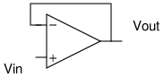
This is the principle behind the simple buffer shown above. If  is initially
  and
and  is initially zero, the op-amp will begin ramping up toward its target value of
  . However, it should be obvious that it never gets there. As soon as climbs ever so slightly above zero, the voltage between the two terminals will become smaller and the target for which the op-amp aims will drop to something like
  . As this process continues, equilibrium will be established when the inverting and non-inverting terminals have the same voltage (well, different by a factor of
  ) - a fact that we will use in just a moment. For the buffer, this means that
  in the steady-state. The purpose of a buffer is to read the signal generated by some voltage source and output a signal that has the exact same voltage but a different current. It is often the case that a waveform used to automate some equipment lacks the current required to do real work like driving a motor. A buffer based on a high-current op-amp comes in handy by boosting the current.
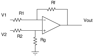
The circuit that I set out to make is the differential amplifier shown above. I found that the required calculations were easy to do if I split the circuit into two parts.
|
|
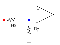
First look at the left side. We know that the voltage drop between the red dot and the ground arrow is  . Since the total resistance along this path is
  , a current of
  flows by Ohm's law. The voltage at the terminal (the potential difference between the blue dot and the ground) is found by multiplying this current:
  . This piece of information carries over to the right side. On the right side, the voltage between the blue dot and ground is the same: . We also know that the voltage between the red dot and ground is simply
  . Subtracting the two, we see that the voltage drop across
  is
is  , giving us a current of
  . Now , the voltage between the green dot and the ground is the voltage between the blue dot and the ground minus the voltage between the blue and green dots. To get this blue to green voltage, we multiply the current by
  . We therefore have:
![\begin{align*}<br />
V_{\textup{out}} &= \frac{V_2 R_{\textup{g}}}{R_2 + R_{\textup{g}}} - R_{\textup{f}} I \\<br />
&= \frac{V_2 R_{\textup{g}}}{R_2 + R_{\textup{g}}} - R_{\textup{f}} \left [ \frac{V_1}{R_1} - \frac{V_2 R_{\textup{g}}}{R_1(R_2 + R_{\textup{g}})} \right ] \\<br />
&= \frac{V_2 R_{\textup{g}} (R_1 + R_{\textup{f}})}{R_1(R_2 + R_{\textup{g}})} - \frac{V_1 R_{\textup{f}}}{R_1}<br />
\end{align*}](/sites/default/files/tex/3f25029c48985b522c15fae687264ca70edfa017.png) |
We have now derived the formula for the output of a differential amplifier. To make the circuit linear, we simply let  and
and  . Our formula then simplifies to
![\[<br />
V_{\textup{out}} = \frac{R_{\textup{f}}}{R_1} (V_2 - V_1)<br />
\]](/sites/default/files/tex/244d1b704a492b0bd13f9be8251a664be26200e4.png) |
So I made this type of circuit and set it up to have a gain of 200 by choosing to be  and to be
  . I also powered the op-amp with a battery by connecting the negative end of the battery to the negative supply pin and the positive end of the battery to the positive supply pin. Unfortunately, I was faced with two problems. The first problem happened when I tested the circuit using a power supply instead of the photodiode. Large signals like
  were correctly amplified to
  but if I shorted the pins and made
  equal to zero Volts, I still saw an output of about
  . A guru reading this can probably already see the rookie mistake that I made but it has to do with one of the most infamous words in electronics: ground!
The supply pins that an op-amp uses (not shown in typical triangle diagrams) accept a positive and a negative voltage. However, the voltage of one pin has no meaning. Electric potential is only defined when you're talking about the difference between two locations in space. So if one is positive and one is negative, that to me sounds like we just need one to be higher than the other. However, there is an implicit ground in the circuit even if we aren't doing anything fancy like connecting it to the Earth. The ground comes from the fact that the output is being measured relative to some other point - which I chose to be the negative terminal of the battery. If I am using the negative terminal of the battery to mean  , I am bound to run into trouble since the negative supply pin is connected to this source as well and not something lower. Op-amps that demand positive and negative voltage in this way are called "split-supply" op-amps. There are "single-supply" op-amps as well, but I wasn't using one. This had the effect of ruining the linearity of the circuit. If one of the "rails" has a voltage of when the op-amp expects it to be lower, it will fail if one tries to bring the output too close to the rail. I solved this problem by dividing the voltage of my
  battery in half with two resistors and using the rail in the middle as my ground. This way the supply pins had voltages of
  and everything started working. I could have also supplied
  if I had used two batteries.
I ran into a second problem when I tried to use this circuit with the photodiode - the photodiode was failing to provide a signal for a  laser. This happened because my circuit did not have a high enough resistance. The current required to put a known voltage across a resistor is inversely proportional to the resistance, by Ohm's joke of a law. Using small resistors may be too strenuous for the photodiode which cannot supply very much current. To solve this problem, I kept the gain at 200 by increasing all my resistors by the same factor. became
  and became
  . Another way to solve it would be to use two more op-amps and buffer each input using the simple buffer shown at the top of this post. This would turn the differential amplifier into what's called an instrumentation amplifier.
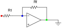
But something else that an electronics guru should see is that I am wasting effort. I could've used a simpler circuit called an inverting amplifier to get the same result. To do this, we simply force to be zero allowing us to take out the  and
and  resistors. This turns our formula into:
![\[<br />
V_{\textup{out}} = -V_1 \frac{R_{\textup{f}}}{R_1}<br />
\]](/sites/default/files/tex/d5472cf9c060a16687006670c2f404f233ab71c5.png) |
Now, we just have to make sure that relative to ground is equal to the potential difference between the two pins of the photodiode. How do we do this? Just hook up one pin of the photodiode to the inverting terminal and ground the other pin. This would have been easy to do... I made my life too complicated!