Main menu
You are here
This Clock Is Ghetto
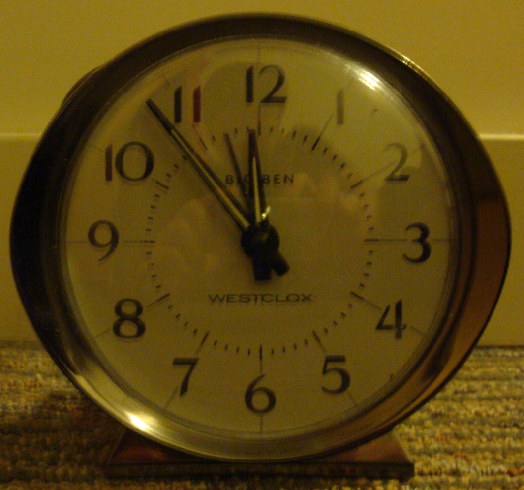
Gaze upon my newest creation. This setup is probably the first of its kind. The black clock showing 2:17 is a digital alarm clock. It sits on top of a clear box holding a circuit board that I made. The white clock showing the wrong time is an analog alarm clock. I can confidently say that when the digital clock reaches the alarm setpoint, the mechanical bells on top of the analog clock will ring.
Even though I study theoretical physics I am very happy to be in the same department as people who are well versed in machining, robotics and other useful endeavours. There is something very satisfying about sitting down to make a device that serves a particular purpose and seeing it through to the end.
This project was necessary because my body is not very good at getting to sleep and even worse at waking up. I have missed classes, buses, trains and planes because of my propensity for ignoring alarms and sleeping in. I routinely hear claims that a person will wake up easily if he or she gets a full 8 hours of sleep. This is complete nonsense in my case. Waking up to an alarm is a painful process if I've only been asleep for 8 hours. It only becomes easy after a 10 hour sleep and it is not uncommon for me to get 12 hours when I'm really tired.

In fact, I recently finished reading Dreamland by David K. Randall. The book is all about sleep and the crazy things people have done in the name of getting a better one. A few things in it were definitely surprising but for the most part, it reinforced the notion that everyone else (besides those with serious sleeping disorders) can get up much more easily than me. But regardless of whether I'm at a genetic disadvantage or just stubbornly refusing to take responsibility for my actions, I have now made a device that will help solve the problem. Some people who are not intimately familiar with my sleep issues ask:
Why don't you just use an electronic alarm?
Because they are not loud enough! My dorm mates from 2007 know as well as my parents that an electronic buzzer will do nothing to get me out of bed. Sometimes when it rings for an hour, I legitimately sleep through it. Other times I am technically awake but I regard it as a soothing sound without developing the slightest inclination to get up. As a test I set a mechanical alarm to ring 10 seconds after my watch alarm. I put both sound sources, one metre away from the microphone and made a recording.
Obviously the physical bell is louder. Software can never tell you how loud something is in dB-SPL. You need a quiet room and a well calibrated reference source for that. But it is pretty simple to use Audacity to measure the ratio between two sound volumes.
In Audacity, I zoomed in a little bit and saw that the amplitude of the loud sound goes up to 80% of the amplitude that would cause clipping to occur. It was really hard to see the soft sound this way so I had to zoom in some more afterward.
This one goes up to 0.010 or maybe 0.015 at the most. Therefore the mechanical bell is 55 times louder than the one on my watch. People who realize this sometimes ask:
Why don't you just use a mechanical alarm?
This is certainly what I would do if I had to only use one but the problem is that mechanical clocks make a ticking sound. It is not loud enough to wake anyone up and it is not the end of the world but the noise is slightly distracting while trying to get to sleep. And contrary to what everyone said would happen, I never really got used to it. This makes the use of an alarm a double edged sword. Not only will the clock cut your sleep short by ringing in the morning... it will also make it take longer for you to get to sleep in the first place. By putting two clocks together in the right way, I have the best of both worlds. A really loud alarm that does not make any ticking sound at night.
So how did I make it? Well I got the electronic alarm clock to trigger a solenoid rather than a piezo-electric buzzer. A solenoid is an electromagnetic device that puts its energy into mechanical motion. Kind of like a motor except instead of making the central rod spin around, a solenoid will make the central rod move inwards (as long as it is made of iron).
A solenoid is simply a coil of wire. If you run current
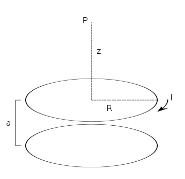
 through a coil, a magnetic field will be produced whose direction is given by the right hand rule. If we are going to talk about the iron rod being "inside" or "outside" the solenoid, we should not approximate the solenoid as having infinite length. The magnetic field
  cannot be calculated exactly for a solenoid of finite length, but if we restrict ourselves to the central axis,
  can be calculated. First solving the problem for a single loop of current, the Biot-Savart Law can be used to show that the magnetic field at point
  in the diagram is:
![\[<br />
B_0(z) = \frac{\mu_0 I}{2} \frac{R^2}{(R^2+z^2)^{\frac{3}{2}}}<br />
\]](/sites/default/files/tex/9165e4d41b1b0a41ce7b6541789abc3d5c7602a6.png) |
If the radius of the wire is  and there is another loop of current sitting on top of this one, point is a distance of
  away from the second loop so we just add
![\[<br />
B_1(z) = \frac{\mu_0 I}{2} \frac{R^2}{(R^2+(z-a)^2)^{\frac{3}{2}}}<br />
\]](/sites/default/files/tex/cde151f108539e17f8c5496a0399e23c3483a172.png) |
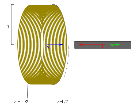
and so on. We can rewrite  where
where  is the length of the solenoid and
  is the number of turns. Adding up all the fields, we get
![\begin{align*}<br />
B(z) &= \frac{\mu_0 I}{2} \sum_{n = -N/2}^{N/2} \frac{R^2}{\left ( R^2 + \left ( z - L \frac{n}{N} \right )^2 \right )^{\frac{3}{2}}} \\<br />
&\approx \frac{\mu_0 I}{2} \int_{N/2}^{N/2} \frac{R^2}{\left ( R^2 + \left ( z - L \frac{n}{N} \right )^2 \right )^{\frac{3}{2}}} \textup{d}n \\<br />
&= \frac{\mu_0 I N}{2 L} \left [ \frac{L/2 - z}{\sqrt{R^2+(L/2 - z)^2}} + \frac{L/2 + z}{\sqrt{R^2+(L/2 + z)^2}} \right ]<br />
\end{align*}](/sites/default/files/tex/dad8aaba2fc8330b335dfc40770d6422d74689c1.png) |
When exposed to this field, any ferromagnetic substance will begin to produce its own field too. Since I don't know enough about the material properties of iron I will approximate the rod as a perfect dipole with moment  . So which way does this induced dipole point? You can figure this out by minimizing energy but an easier way is to think of the familiar situation where you stick a piece of iron beside a permanent magnet. The metal and the magnet do not repel, they attract. This means that the North pole of one is right beside the South pole of the other and their dipole moments point in the same direction. We can solve for the force of attraction as
![\begin{align*}<br />
F(z) &= -\frac{\textup{d} U}{\textup{d}z} \\<br />
&= \frac{\textup{d}}{\textup{d}z} \textbf{m} \cdot \textbf{B}(z) \\<br />
&= \frac{m \mu_0 I N}{2 L} \left [ \frac{\left ( \frac{L}{2} + z \right )^2}{\left ( R^2+ \left ( \frac{L}{2} + z \right )^2 \right )^{3/2}} - \frac{\left ( \frac{L}{2} - z \right )^2}{\left ( R^2+ \left ( \frac{L}{2} - z \right )^2 \right )^{3/2}} + \frac{1}{\sqrt{R^2+ \left ( \frac{L}{2}+z \right )^2}} - \frac{1}{\sqrt{R^2+ \left ( \frac{L}{2}-z \right )^2}} \right ]<br />
\end{align*}](/sites/default/files/tex/81755829b4212e567a4914d2db3ae9327ded8a67.png) |
A dipole that is in the centre feels no force, and a dipole that is infinitely far away feels no force. But as the dipole moves in from infinity, the force responsible for the pulling increases. There is something that makes this increase even more pronounced. We put the permeability of free space
 in our equations above. But really we should use the permeability of the medium inside the solenoid. As the iron rod travels inward, an increasingly large fraction of the matter inside becomes iron rather than air. Since
  for iron is hundreds of times larger than , we can see that when the current is turned on, a rod sitting near the edge of the solenoid will feel a slight pull, whereas a rod that is already mostly inside will just get yanked.
Once I realized that a solenoid would be the best thing to use, I set out to make this circuit. The best place to work was the Engineering Physics Project Lab at UBC. It is very organized despite having a huge assortment of tools and the people there are very friendly to newcomers. They said I could help myself to almost anything in the lab but I ordered the major pieces myself from DigiKey because I didn't want to be a moocher.
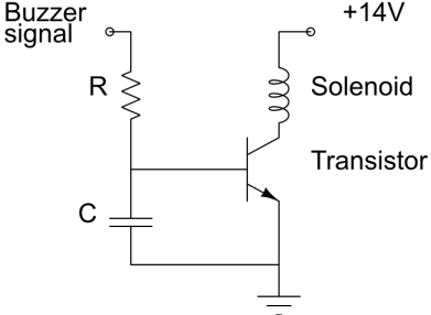
The switch that completes the circuit is an NPN transistor. The base voltage causing the switch to close should not come directly from the alarm because this signal pulsates. The buzzer spends one second on, one second off, the next second on, the next second off, etc. I didn't want the solenoid turning on and off. Therefore I decided to put the alarm signal through a low-pass filter first. If the resistance and capacitance are very large, this converts a square wave into its average value which has the ability to make the solenoid turn on permanently. I planned to have three pins connected to the electronic clock: one providing the ground, one providing the alarm signal and one providing the
 used by the components in the clock. The first one was easy because a pin inside was labelled "GND".
The second one was a little weird. When I opened up the RCA clock and found the buzzer it had a red wire and a black wire coming out of it. Common sense suggests that the black one is always  right? And the red one should probably alternate between and when the alarm is ringing? This turned out not to be the case. The red wire was always at . Using an oscilloscope I saw that the black wire alternated between when there was no beeping and
  when there was beeping. Therefore when I disconnected the buzzer, I decided to connect the black wire to my low-pass filter. That way reaching the alarm time would cause this voltage to ramp from to
  which is more than enough to change the state of a transistor.
Getting the last pin was so annoying that I eventually gave up. I needed a source to drive the solenoid but I could not use the red buzzer wire for instance because of its inability to supply high currents. Most digital circuits are limited to very low currents. This saves energy but it is one of the reasons why the alarms are so soft. Since the alarm plugged into the wall (which can supply high currents) I figured that if I made a solder connection somewhere between the transformer and the circuit board, I would be able to get at the "real" power which can put across a demanding load. I couldn't find the right place though.
The clock was using a pretty standard scheme to convert voltage from the AC frequency  . The grid power of
  connects to a transformer (basically two inductors) which lowers it to
  . This goes through a bridge rectifier which turns it into
  . After this, a capacitor is used to damp away the oscillations and get an approximate DC . None of these should lower the current because current limiting requires at least one resistor. I was therefore puzzled about why all the connections I made were unable to drive the solenoid. There weren't any large resistors I could find that were heating up and as I frantically tried more and more connections, I started to see sparks fly. So instead of breaking everything, I decided to just get my own power supply. This obviously works but it means that my hybrid alarm clock requires two free outlets which is tacky. Now I'm starting to think that the missing resistors are located inside the sealed enclosure of the first transformer. This is the safest possible thing to manufacture but it is not very good for my purposes. There are clock kits for hobbyists that don't have this problem but there are only so many times I'm prepared to change the plan.
I connected this circuit to the digital clock and got it to work. All that was left to do was to glue or tape or weld or solder it onto this analog clock. For this part I have to thank Jason Radel for getting me into the student machine shop and cutting the metal that I needed. People who want to use the shop whether it's for easy things or hard things have to take a 40 hour course. I wish they had finer degrees like the Project Lab but I guess they need to cover their asses. Viewed from the side and without the back panel, the clock looks like:
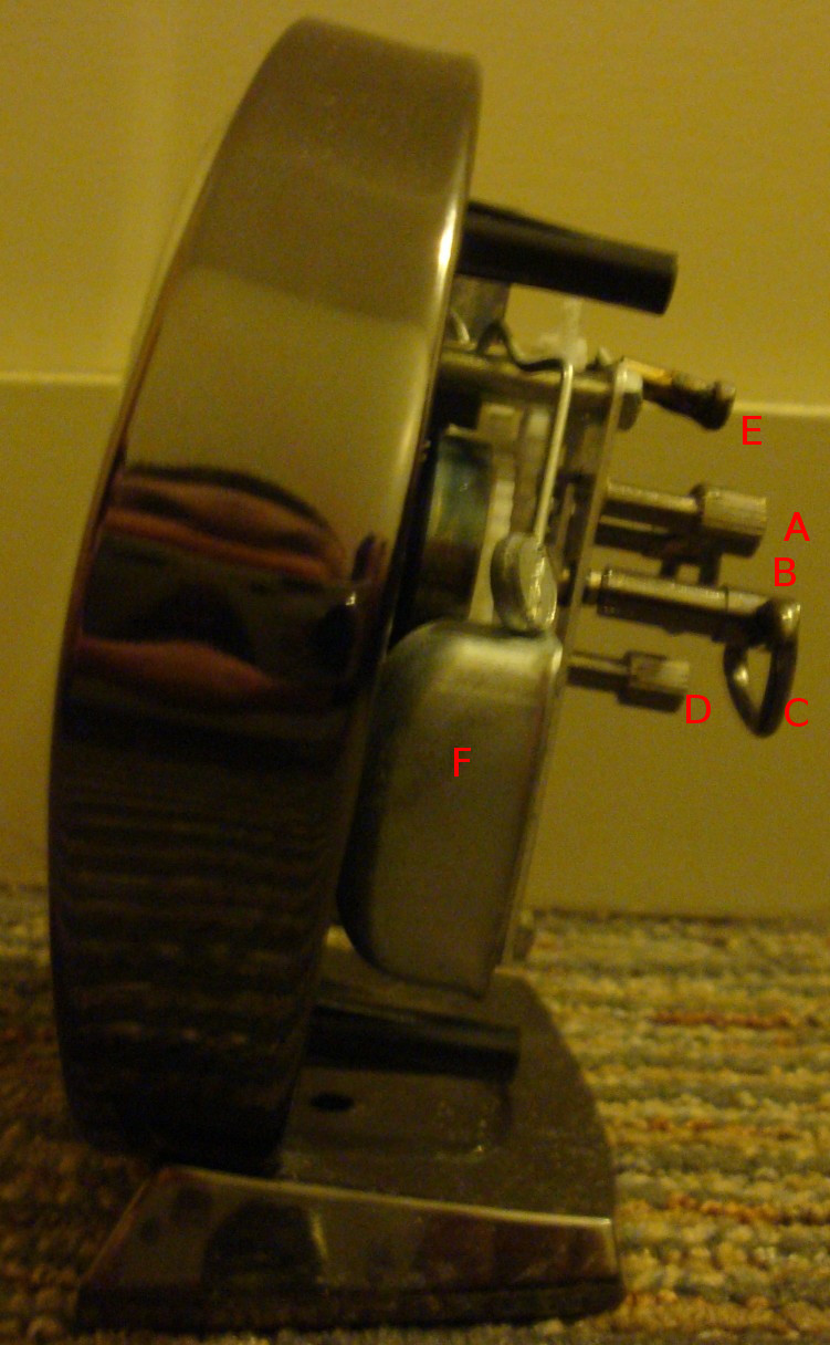
Winding knob A will adjust the time for which the alarm is set. Winding knob D will adjust the time of the clock. Knob B puts energy into the spring that is used for keeping time while knob C puts energy into the spring that allows the hammer to strike the bell. However, the loud part F will only work when the pin E is pulled out. If it is pushed in, the alarm is off so I decided that I would epoxy the solenoid to pin E. That way I could adjust the hands of the clock to match the alarm hand and the ringing would commence as soon as the solenoid was triggered. There were some thorny issues with this, however. How much force does it take to pull the pin? I measured this by hanging a bunch of weights off it and found that the pin will move with
 of force applied. If you look at the datasheet for the solenoid I ordered, you will see that it can supply this much force if the rod starts off 1/16 of an inch (remember what I said about force increasing the further in you go) from the back of the coil. This seems okay, but one thing you will also see on the datasheet is that this is a latching solenoid.
This means that you can pull the rod in with a high current but getting the rod back out is not as simple as turning the current off. The black boxes above are strong permanent magnets that kick in once the iron crossbar gets too close. One thing this does is make the solenoid polarity sensitive. Remember when I said that the North pole of the iron rod is beside the South pole of the solenoid? That is not necessarily true in a latching solenoid. Before the current turns on, the permanent magnet is already polarizing the iron and making it so the North pole of the iron is beside the South pole of the permanent magnet. Depending on which way the wires are, turning on the current can then give the solenoid the opposite alignment and push the iron rod out. This was neat but it wasn't a real problem. The real problem was that the position of the iron rod had to be adjusted with ridiculous precision. I soon found out that if the extension was a little bit more than 1/16 of an inch, the coil would be unable to exert enough force. Also if it was a little bit less than 1/16 of an inch, the permanent magnets would make it move in right away and it would no longer be able to pull the clock's pin at a programmable time. There were a few times when I managed to get the position just right, but then another stupid thing happened.
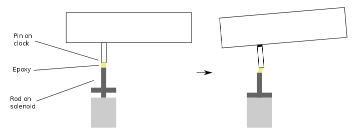
The pin that I had to pull was not in the centre of the clock. This made the solenoid exert a torque on the clock and turn it relative to the metal base. Epoxy does not give a very good bond between two pieces of metal to begin with. A few turns like this is more than enough to break the bond. Even worse is that when the solenoid pulls the pin and moves all the way to the back like this, it requires about
 of force to pull the magnets apart and reset it. If the rotation doesn't break the epoxy, this will. After much frustration, I decided to use a different mechanical clock and a different solenoid!
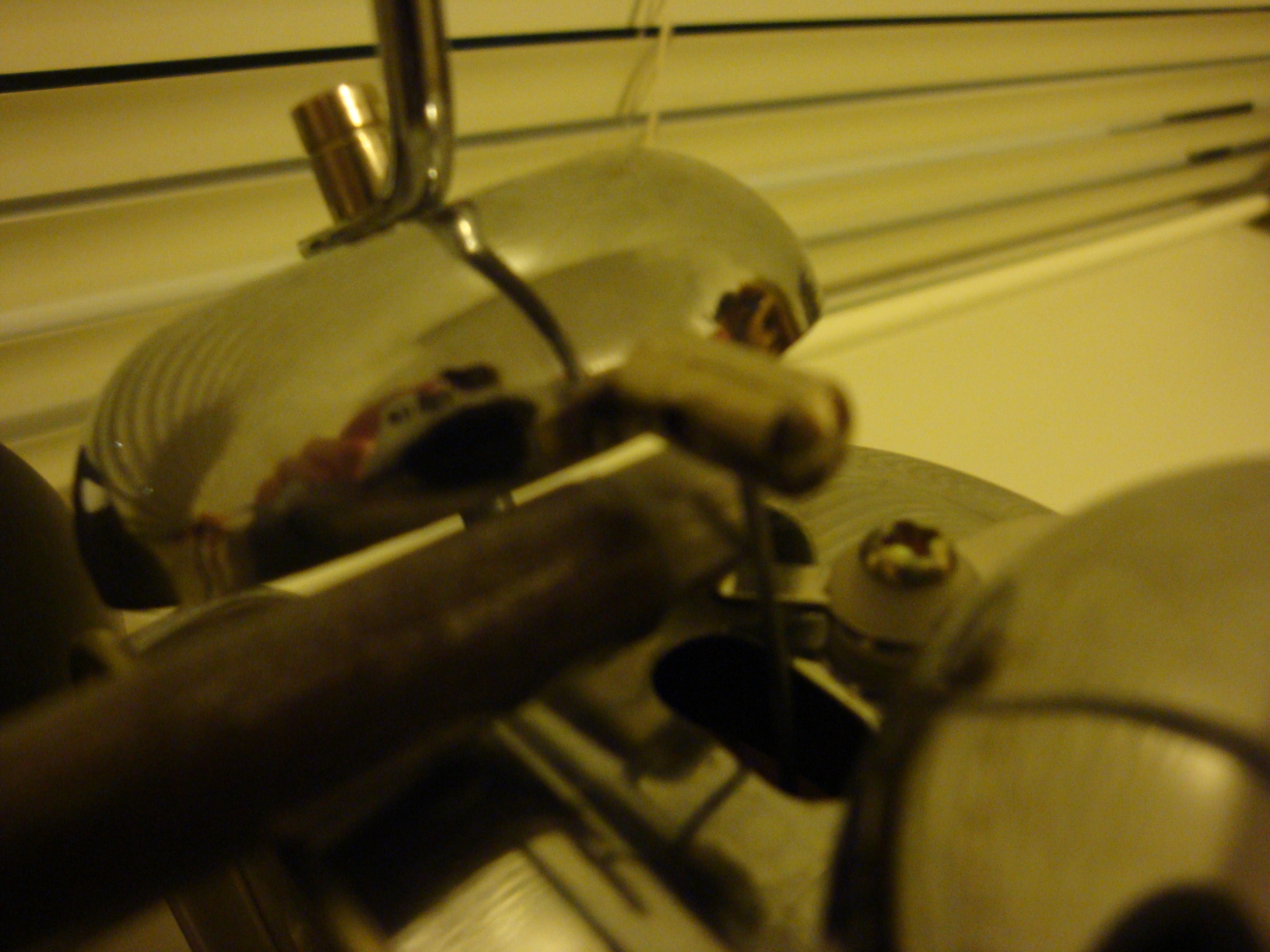
Not wanting to wait for another order, I traded solenoids with the Project Lab and got a nice non-latching one. I also went with the alarm clock that I had been using as a backup over all of this time. The wind-up knobs are exactly the same as what I already described but the bells are accessible from the outside. The hammer moves back and forth between them until its motion is interrupted by a movable metal stick on top. Using the electronically controlled solenoid instead of this manually controlled metal stick was straightforward. Jason and I built this stand for the solenoid:
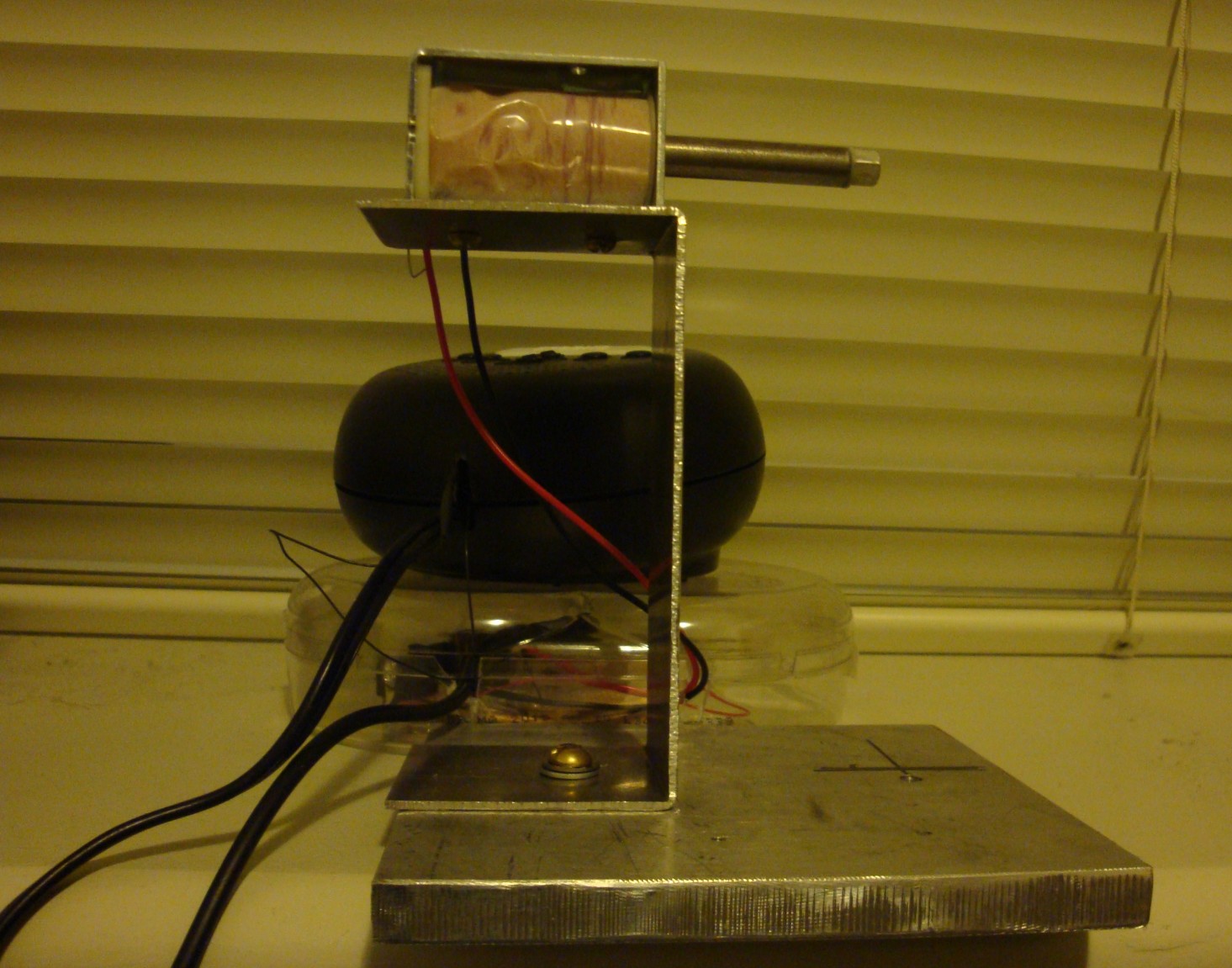
You can see the two cords coming out of the setup. One powers the solenoid, the other powers the electronic clock. The plastic box holding the circuit used to be a box of chocolates. Sliding in the mechanical clock so that the hammer rests up against the solenoid rod is very easy. It stays that way for the entire night and then when the alarm setpoint is reached it moves out of the way.
This has woken me up successfully five days in a row. The probability of it failing is about the same as the probability of a store bought mechanical alarm clock failing anyway due to one of the gears getting stuck. The only thing I have to worry about now is carrying this thing very carefully the next time I move!